前回加速度センサの計測結果をTFT液晶パネルに表示しましたが、今回はそのプログラムの中身を読み解いていきながらTFTモニタの扱いを学んでいきたいと思います!
今回の電子工作レシピ
完成までの時間目安:60分
必要なパーツ
- Arduino本体(Arduino UNO R3)https://www.switch-science.com/catalog/789/
- ロームセンサ評価キット http://www.rohm.co.jp/web/japan/sensor-shield-support
- TFT液晶パネル(sainsmart 1.8) https://www.amazon.co.jp/dp/B008HWTVQ2
目次
- ArduinoでTFT液晶モニタに表示する
- 加速度センサの数値をグラフにしてみる
- まとめ
1.ArduinoでTFT液晶モニタに表示する
今回利用したTFTモニタはsainsmart社のST7735Rというモニタです。このモニタはArduino以外でもRaspberry Piなどでも利用が可能な小型のディスプレイになっています。microSDカードのスロットも実装されているのでデータの読み書きもできるのですが、今回はTFTモニタの表示のみ試してみます。
まず、ArduinoとTFTモニタを接続していきます。
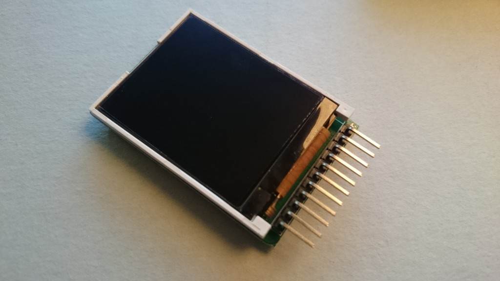
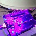
写真1 TFTモニタ
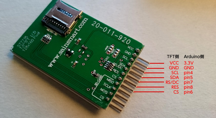
写真2 TFTモニタの裏側
ちなみに、基板に書かれているピンの名称や役割ですが、
- VCC – 電源入力(Correction Voltage)
- GND – グランド(Ground)
- SCL – シリアルクロックライン(Serial Clock Line)
- SDA – シリアルデータライン(Serial Data Line)
- RS/DC – コマンド/データセレクション(Command/Data Selection)
- RES – リセット(LCD Controller Reset)
- CS – チップ選択(Chipselect for TF Card)
という感じになっているようです。
ArduinoとTFTモニタの接続が完了したらサンプルプログラムを動かしてみます。
TFTモニタのライブラリをArduino用に適用する
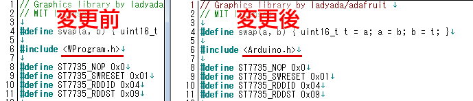
このTFTモニタはST7735Rというライブラリを利用してArduinoで表示をすることができるのですが、このST7735RはそのままではArduinoで利用することができないため、ライブラリファイルの一部を変更する必要があります。
上記のURLからページの最下部に「REFERENCE PROJECTS」という項目があり、そこにこのTFT液晶をラズベリーパイで動かすための手順が書かれています。日本語で解説されている方もいますね。ライブラリやサンプルコード、ドキュメントなどの一式をダウンロードが完了したら、圧縮ファイルを解凍した後、必要なファイルを書き換えていきます。
「ST7735.h」をテキストが編集できるエディタで開いた後、4行目の図で示している部分を変更します。これでArduinoでも利用することができます。
ファイルの変更が完了したら、解凍した「TFT18」ディレクトリを再度zipなどで圧縮して、Arduino(もしくはArduino Create)のAdd Libraryからライブラリとして追加するか、Arduinoのインストールされているディレクトリにある「libraries」ディレクトリの配下に設置してライブラリを読み込んでください。
読み込みが完了したら、スケッチのサンプルから「TFT18」-「graphictest」を動かしてみます。
サンプルプログラムを見るとなかなかスムーズに表示されているのが確認できますね。
サンプルプログラム – graphictest
//ピンの設定
#define sclk 4
#define mosi 5
#define cs 6
#define dc 7
#define rst 8

//利用する色番号
#define	BLACK           0x0000
#define	BLUE            0x001F
#define	RED             0xF800
#define	GREEN           0x07E0
#define CYAN            0x07FF
#define MAGENTA         0xF81F
#define YELLOW          0xFFE0
#define WHITE           0xFFFF

#include <ST7735.h>
#include <SPI.h>

ST7735 tft = ST7735(cs, dc, mosi, sclk, rst);


void fillpixelbypixel(uint16_t color) {
  for (uint8_t x=0; x < tft.width; x++) {
    for (uint8_t y=0; y < tft.height; y++) {
      tft.drawPixel(x, y, color);
    }
  }
  delay(100);
}

void setup(void) {
  Serial.begin(9600);
  Serial.print("hello!");
  tft.initR();               // initialize a ST7735R chip

  Serial.println("init");
  tft.writecommand(ST7735_DISPON);

  uint16_t time = millis();
  tft.fillScreen(BLACK);
  time = millis() - time;

  Serial.println(time, DEC);
  delay(500);

  //
  tft.fillScreen(BLACK);
  testdrawtext("Lorem ipsum dolor sit amet, consectetur adipiscing elit. Curabitur adipiscing ante sed nibh tincidunt feugiat. Maecenas enim massa, fringilla sed malesuada et, malesuada sit amet turpis. Sed porttitor neque ut ante pretium vitae malesuada nunc bibendum. Nullam aliquet ultrices massa eu hendrerit. Ut sed nisi lorem. In vestibulum purus a tortor imperdiet posuere. ", WHITE);
  delay(1000);

  //a single pixel
  tft.drawPixel(tft.width/2, tft.height/2, GREEN);
  delay(500);

  // line draw test
  testlines(YELLOW);
  delay(500);

  // optimized lines
  testfastlines(RED, BLUE);
  delay(500);

  testdrawrects(GREEN);
  delay(500);

  testfillrects(YELLOW, MAGENTA);
  delay(500);

  tft.fillScreen(BLACK);
  testfillcircles(10, BLUE);
  testdrawcircles(10, WHITE);

  Serial.println("done");
  delay(1000);
}

void loop() {
  tft.writecommand(ST7735_INVON);
  delay(500);
  tft.writecommand(ST7735_INVOFF);
  delay(500);
}

void testlines(uint16_t color) {
   tft.fillScreen(BLACK);
   for (uint16_t x=0; x < tft.width; x+=6) {
     tft.drawLine(0, 0, x, tft.height-1, color);
   }
   for (uint16_t y=0; y < tft.height; y+=6) {
     tft.drawLine(0, 0, tft.width-1, y, color);
   }

   tft.fillScreen(BLACK);
   for (uint16_t x=0; x < tft.width; x+=6) {
     tft.drawLine(tft.width-1, 0, x, tft.height-1, color);
   }
   for (uint16_t y=0; y < tft.height; y+=6) {
     tft.drawLine(tft.width-1, 0, 0, y, color);
   }

   tft.fillScreen(BLACK);
   for (uint16_t x=0; x < tft.width; x+=6) {
     tft.drawLine(0, tft.height-1, x, 0, color);
   }
   for (uint16_t y=0; y < tft.height; y+=6) {
     tft.drawLine(0, tft.height-1, tft.width-1, y, color);
   }

   tft.fillScreen(BLACK);
   for (uint16_t x=0; x < tft.width; x+=6) {
     tft.drawLine(tft.width-1, tft.height-1, x, 0, color);
   }
   for (uint16_t y=0; y < tft.height; y+=6) {
     tft.drawLine(tft.width-1, tft.height-1, 0, y, color);
   }

}

void testdrawtext(char *text, uint16_t color) {
  tft.drawString(0, 0, text, color);
}

void testfastlines(uint16_t color1, uint16_t color2) {
   tft.fillScreen(BLACK);
   for (uint16_t y=0; y < tft.height; y+=5) {
     tft.drawHorizontalLine(0, y, tft.width, color1);
   }
   for (uint16_t x=0; x < tft.width; x+=5) {
     tft.drawVerticalLine(x, 0, tft.height, color2);
   }
}

void testdrawrects(uint16_t color) {
 tft.fillScreen(BLACK);
 for (uint16_t x=0; x < tft.width; x+=6) { tft.drawRect(tft.width/2 -x/2, tft.height/2 -x/2 , x, x, color); } } void testfillrects(uint16_t color1, uint16_t color2) { tft.fillScreen(BLACK); for (uint16_t x=tft.width-1; x > 6; x-=6) {
   tft.fillRect(tft.width/2 -x/2, tft.height/2 -x/2 , x, x, color1);
   tft.drawRect(tft.width/2 -x/2, tft.height/2 -x/2 , x, x, color2);
 }
}

void testfillcircles(uint8_t radius, uint16_t color) {
  for (uint8_t x=radius; x < tft.width; x+=radius*2) {
    for (uint8_t y=radius; y < tft.height; y+=radius*2) {
      tft.fillCircle(x, y, radius, color);
    }
  }
}

void testdrawcircles(uint8_t radius, uint16_t color) {
  for (uint8_t x=0; x < tft.width+radius; x+=radius*2) {
    for (uint8_t y=0; y < tft.height+radius; y+=radius*2) {
      tft.drawCircle(x, y, radius, color);
    }
  }
}
上記のプログラムの中で、TFTの操作で中心となる関数は下記になります。
-
tft.drawPixel(x,y,color); - 指定した位置(x,y)に指定した色(color)のドットを表示します。
-
tft.drawCircle(x, y, radius, color); - 指定した位置(x,y)で指定した半径(radius)の円を描きます。
-
tft.fillRect(x1,y1, x2, y2, color); - 指定した位置1(x1,y1)から位置2(x2,y2)までの幅と高さで長方形を塗ります。
-
tft.drawString(x, y, text, color); - 指定した位置(x,y)に指定した色(color)でテキストを表示します。
-
tft.fillScreen(0x0000); - 指定した色でモニタ全体を塗ります
他にもいくつか関数はありますが、基本的にこれだけ使うだけでも豊かな表現が可能です。
2.加速度センサの数値をグラフにしてみる
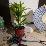
TFTモニタの動作が確認できたら、次は加速度センサの値をTFTモニタに表示してみます。センサ評価キットの場合、加速度センサをキットに取り付けさえすれば、基本的にTFTモニタ側の配線は変更する必要はありません。
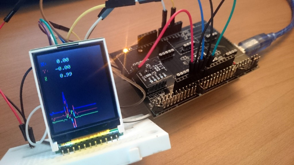
写真3 加速度センサとTFTモニタ
加速度センサの数値を表示するプログラム
#include <Wire.h>
#include <KX022.h>
#include <ST7735.h>
#include <SPI.h>
// You can use any (4 or) 5 pins
#define sclk 4
#define mosi 5
#define cs 6
#define dc 7
#define rst 8 // you can also connect this to the Arduino reset
// Color definitions
#define BLACK 0x0000
#define BLUE 0x001F
#define RED 0xF800
#define GREEN 0x07E0
#define CYAN 0x07FF
#define MAGENTA 0xF81F
#define YELLOW 0xFFE0
#define WHITE 0xFFFF
ST7735 tft = ST7735(cs, dc, mosi, sclk, rst);
KX022 kx022(KX022_DEVICE_ADDRESS_1E);
int _cnt = 0;
//グラフ初期位置
int _xc = 120;
int _yc = 130;
int _zc = 140;
void fillpixelbypixel(uint16_t color) {
for (uint8_t x=0; x < tft.width; x++) {
for (uint8_t y=0; y < tft.height; y++) {
tft.drawPixel(x, y, color);
}
}
delay(100);
}
void setup(void) {
byte rc;
Serial.begin(9600);
while (!Serial);
Wire.begin();
tft.initR(); // initialize a ST7735R chip
rc = kx022.init();
tft.fillScreen(BLACK);
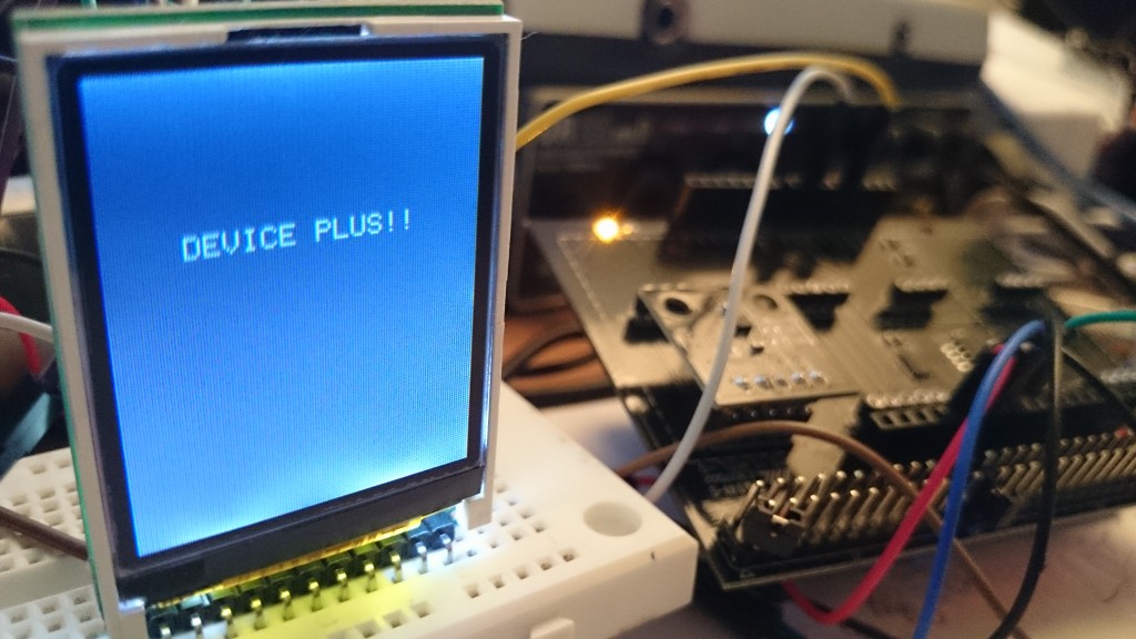
1.DEVICE PLUSの文字を表示
testdrawtext("DEVICE PLUS!!", WHITE,25,50);
delay(1000);
tft.fillScreen(BLACK);
}
void loop() {
//KX022
byte rc;
float acc[3];
//2.加速度センサの値を取得する
rc = kx022.get_val(acc);
if (rc == 0) {
Serial.write("KX022 (X) = ");
Serial.print(acc[0]);
Serial.println(" [g]");
Serial.write("KX022 (Y) = ");
Serial.print(acc[1]);
Serial.println(" [g]");
Serial.write("KX022 (Z) = ");
Serial.print(acc[2]);
Serial.println(" [g]");
Serial.println();
//float型をchar型に変換
char xVal[10];
dtostrf(acc[0], 5, 2, xVal);
char yVal[10];
dtostrf(acc[1], 5, 2, yVal);
char zVal[10];
dtostrf(acc[2], 5, 2, zVal);
//TFT液晶に変換
//tft.fillScreen(BLACK);
tft.fillRect(0,0, 120, 60, BLACK);
testdrawtext("X:", RED, 5, 15);
testdrawtext(xVal, WHITE, 30, 15);
testdrawtext("Y:", BLUE, 5, 30);
testdrawtext(yVal, WHITE, 30, 30);
testdrawtext("Z:", GREEN, 5, 45);
testdrawtext(zVal, WHITE, 30, 45);
//3.グラフを描画
int x = int(acc[0]*100)+120;
int y = int(acc[1]*100)+130;
int z = int(acc[2]*100)+40;
tft.drawLine(_cnt-1, _xc, _cnt, x, RED);
tft.drawLine(_cnt-1, _yc, _cnt, y, BLUE);
tft.drawLine(_cnt-1, _zc, _cnt, z, GREEN);
_cnt++;
//画面の端までいったらリセット
if(_cnt > 120){
_cnt = 0;
tft.fillScreen(BLACK);
}
_xc = x;
_yc = y;
_zc = z;
delay(10);
}
delay(10);
}
void testlines(uint16_t color) {
tft.fillScreen(BLACK);
for (uint16_t x=0; x < tft.width; x+=6) {
tft.drawLine(0, 0, x, tft.height-1, color);
}
for (uint16_t y=0; y < tft.height; y+=6) {
tft.drawLine(0, 0, tft.width-1, y, color);
}
tft.fillScreen(BLACK);
for (uint16_t x=0; x < tft.width; x+=6) {
tft.drawLine(tft.width-1, 0, x, tft.height-1, color);
}
for (uint16_t y=0; y < tft.height; y+=6) {
tft.drawLine(tft.width-1, 0, 0, y, color);
}
tft.fillScreen(BLACK);
for (uint16_t x=0; x < tft.width; x+=6) {
tft.drawLine(0, tft.height-1, x, 0, color);
}
for (uint16_t y=0; y < tft.height; y+=6) {
tft.drawLine(0, tft.height-1, tft.width-1, y, color);
}
tft.fillScreen(BLACK);
for (uint16_t x=0; x < tft.width; x+=6) {
tft.drawLine(tft.width-1, tft.height-1, x, 0, color);
}
for (uint16_t y=0; y < tft.height; y+=6) {
tft.drawLine(tft.width-1, tft.height-1, 0, y, color);
}
}
void testdrawtext(char *text, uint16_t color,int x,int y) {
tft.drawString(x, y, text, color);
}
void testfastlines(uint16_t color1, uint16_t color2) {
tft.fillScreen(BLACK);
for (uint16_t y=0; y < tft.height; y+=5) {
tft.drawHorizontalLine(0, y, tft.width, color1);
}
for (uint16_t x=0; x < tft.width; x+=5) {
tft.drawVerticalLine(x, 0, tft.height, color2);
}
}
void testdrawrects(uint16_t color) {
tft.fillScreen(BLACK);
for (uint16_t x=0; x < tft.width; x+=6) { tft.drawRect(tft.width/2 -x/2, tft.height/2 -x/2 , x, x, color); } } void testfillrects(uint16_t color1, uint16_t color2) { tft.fillScreen(BLACK); for (uint16_t x=tft.width-1; x > 6; x-=6) {
tft.fillRect(tft.width/2 -x/2, tft.height/2 -x/2 , x, x, color1);
tft.drawRect(tft.width/2 -x/2, tft.height/2 -x/2 , x, x, color2);
}
}
void testfillcircles(uint8_t radius, uint16_t color) {
for (uint8_t x=radius; x < tft.width; x+=radius*2) {
for (uint8_t y=radius; y < tft.height; y+=radius*2) {
tft.fillCircle(x, y, radius, color);
}
}
}
void testdrawcircles(uint8_t radius, uint16_t color) {
for (uint8_t x=0; x < tft.width+radius; x+=radius*2) {
for (uint8_t y=0; y < tft.height+radius; y+=radius*2) {
tft.drawCircle(x, y, radius, color);
}
}
}
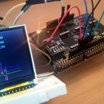
上記のプログラムを起動させると、前回紹介した加速度センサの値のグラフが表示されます。
プログラムの流れとしては
- setup内で「DEVICE PLUS!!」の文字を表示
- 加速度センサの値を取得して整数に直す
- 値をもとにグラフとテキストを表示
という流れになっています。今回はフレームごとにx軸に1を足して左から右にグラフが描画されるようにしています。端っこの120pxまでいった場合はグラフをdrawrectでクリアしています。また、上部の数字も同じようにフレーム毎に、drawrectで更新をかけています。
まとめ
センサ評価キットを使って、これまでたくさんのセンサや部品を扱ってきました。今回の小型のTFTモニタもそうですが、ArduinoやRaspberry Piなどの小さなコンピュータが手軽に扱えることで、普段私達が使っている普通のパソコンではできないことがアイデア次第でできるようになりました。普通のパソコンは高価なのでなかなか乱暴に扱うことができませんが、Arduinoなどは普通のパソコンに比べて比較的安価なので、たとえば今回のTFTモニタとArduino Pro miniなどを組み合わせて時計や小型ゲームを作ってみることもできますし、センサ評価キットのセンサを載せてデータロガーを作成するなんてことも可能です。