今回は、ちょっと変わったArduinoの使い方を紹介します。一見、これまでの連載でも使っているArduino Pro Miniのようにも見えますが、このArduinoは違う種類になります。その名も「Arduino Pro Micro」。MiniがMicroになっただけで、大きさもあまり変わらずどっちがどっちかわからなくなるような命名ですが、このArduinoはPCに接続した際にマウスやキーボードなどのHID(ヒューマン・インターフェイス・デバイス)として認識させることができるちょっと変わったArduinoなのです。今回は、このArduino Pro Microを利用してArduinoからPCを操作してみたいと思います。
今回の電子工作レシピ
完成までの時間目安:60分
必要なパーツ
目次
- Arduino Pro Microについて
- HIDとして認識させてみる
- ジョイスティックを使ったマウスデバイスの作成
- まとめ
1.Arduino Pro Microについて
Arduino Pro Microとは、ATmega32U4というチップを搭載したArduino(UNOなどはATmega328Pなどを搭載)で、このチップでは、USB接続された際にキーボードやマウスなどのヒューマンインタフェースデバイス(HID)のふりをすることができるという大きな特徴があります。このATmega32U4を搭載しているArduinoはこのPro Microのほか、Arduino Leonardoというボードが有名です。
プログラムを書き込む際は、「Arduino Leonardo」というボードを選択して書き込むことができます。
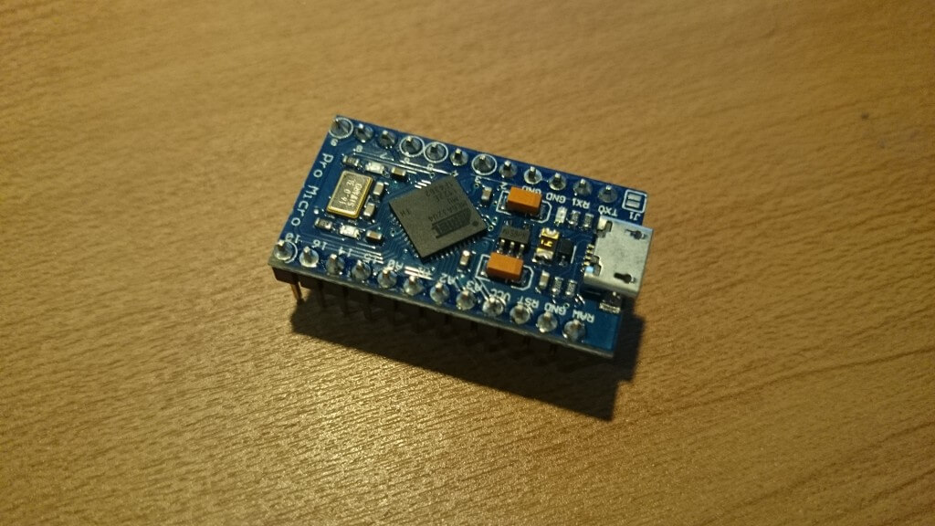
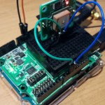
一見Arduino Pro MiniとそっくりなArduino Pro Micro。
ただし、Pro Miniはシリアルコネクタ接続なのに比べて、Pro Microはスマートフォンなどが接続できる形式のUSBコネクタがついています。
2.HIDとして認識させてみる
さっそくArduino Pro Microにサンプルプログラムを書き込んでHIDとしてパソコンに認識させてみます。
Arduino IDEの「ファイル」-「スケッチの例」-「09.USB」-「Keyboard」-「KeyboardMessage」のプログラムを実行してみます。
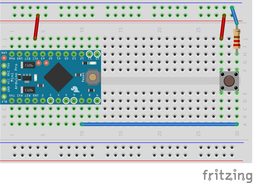
このプログラムでは、4番ピンにスイッチをつけたシンプルな回路を作成して、4番ピンが押されたら押された回数のカウンターをキーボード入力で表示するプログラムになっています。
(今回は4番から7番ピンに変えています)
#include "Keyboard.h"

const int buttonPin = 7; // input pin for pushbutton
int previousButtonState = HIGH; // for checking the state of a pushButton
int counter = 0; // button push counter

void setup() {
 // make the pushButton pin an input:
 pinMode(buttonPin, INPUT);
 // initialize control over the keyboard:
 Keyboard.begin();
}

void loop() {
 // read the pushbutton:
 int buttonState = digitalRead(buttonPin);
 // if the button state has changed,
 if ((buttonState != previousButtonState)
 // and it's currently pressed:
 && (buttonState == HIGH)) {
 // increment the button counter
 counter++;
 // type out a message
 Keyboard.print("You pressed the button ");
 Keyboard.print(counter);
 Keyboard.println(" times.");
 }
 // save the current button state for comparison next time:
 previousButtonState = buttonState;
}
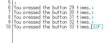
実際にプログラムを書き込んで、メモ帳などを開いたうえで、ボタンを押すたびにキーボードを触っていないのに上記の記述とともにカウントアップしていきます。
なんか、こんな手軽にUSB機器が作れてしまうなんていうのは、夢が広がりますね!
3.ジョイスティックを使ったマウスデバイスの作成
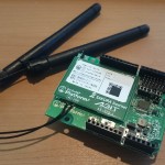
HIDとして利用ができることがわかりましたので、実際に部品と組み合わせてマウスデバイスを作ってみたいと思います。今回は以前ラジコン制作で1度使ったことがあるジョイスティックを使って、ジョイスティックとタクトスイッチでマウスの代わりになるようなデバイスにしてみます。
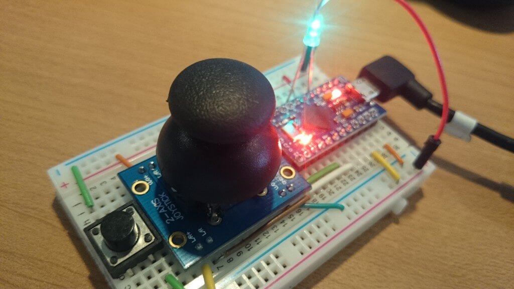
まず先に、ジョイスティックを使って上下左右とスイッチの状態を取得できるようにプログラムを用意します。
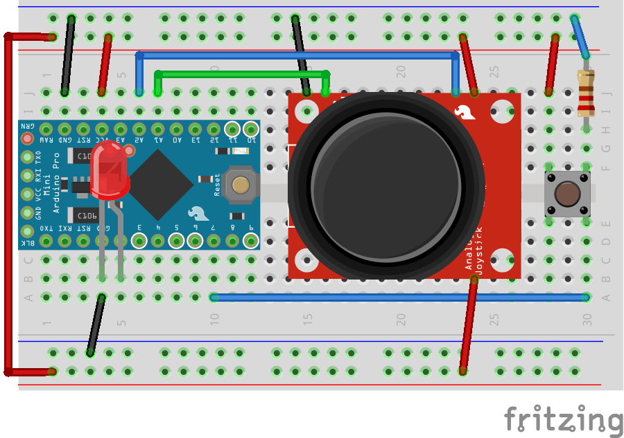
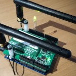
回路は、先ほどのタクトスイッチの回路に加えていきます。ジョイスティックと後に利用するLEDを2番ピンに接続しています。
const int _UDPIN = A0; // UD入力
const int _LRPIN = A1; // LR入力
const int _SWPIN = 7; // デジタルピン
int _UD = 0; // 上下の値
int _LR = 0; // 左右の値

void setup() {
 Serial.begin(9600);
 pinMode(_SWPIN,INPUT) ;
}

void loop() {
 _UD = analogRead(_UDPIN);
 _LR = analogRead(_LRPIN);
 Serial.print("UP-DOWN:");
 Serial.print(_UD, DEC);
 Serial.print(" - Left-Rright:");
 Serial.println(_LR, DEC);
 if (digitalRead(_SWPIN) == HIGH) {
 Serial.println("switch on");
 }
 delay(100);
}
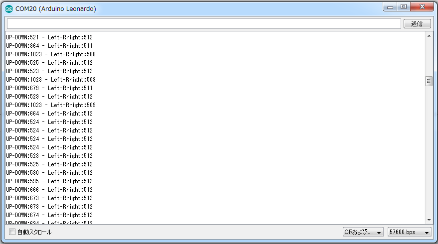
プログラムを書き込んでジョイスティックをぐりぐり回すと数値が変わるのが確認できました。
では、実際にジョイスティックの値をマウス座標に変換させていきます。このプログラムについても実はサンプルに用意されているので、それを使ってみます。「ファイル」-「スケッチの例」-「09.USB」-「Mouse」-「JoystickMouseControl」を選択してください。
このプログラムを実行すると上下はアナログのA2番ピン、左右はA1番ピンの数値をマウス座標に反映させるようなプログラムになっています。また、2番に5Vの電源を入れることでスイッチになっていますので、2番とVCCを結線するか、スイッチを挟むことでデバイスのオンオフもできます。
#include "Mouse.h"

// set pin numbers for switch, joystick axes, and LED:
const int switchPin = 5; // switch to turn on and off mouse control
const int mouseButton = 7; // input pin for the mouse pushButton
const int xAxis = A1; // joystick X axis
const int yAxis = A2; // joystick Y axis
const int ledPin = 2; // Mouse control LED

// parameters for reading the joystick:
int range = 12; // output range of X or Y movement
int responseDelay = 5; // response delay of the mouse, in ms
int threshold = range / 4; // resting threshold
int center = range / 2; // resting position value

boolean mouseIsActive = false; // whether or not to control the mouse
int lastSwitchState = LOW; // previous switch state

void setup() {
pinMode(switchPin, INPUT); // the switch pin
pinMode(ledPin, OUTPUT); // the LED pin
// take control of the mouse:
Mouse.begin();
}

void loop() {
// read the switch:
int switchState = digitalRead(switchPin);
// if it's changed and it's high, toggle the mouse state:
if (switchState != lastSwitchState) {
if (switchState == HIGH) {
mouseIsActive = !mouseIsActive;
// turn on LED to indicate mouse state:
digitalWrite(ledPin, mouseIsActive);
}
}
// save switch state for next comparison:
lastSwitchState = switchState;

// read and scale the two axes:
int xReading = readAxis(A0);
int yReading = readAxis(A1);

// if the mouse control state is active, move the mouse:
if (mouseIsActive) {
Mouse.move(xReading, yReading, 0);
}

// read the mouse button and click or not click:
// if the mouse button is pressed:
if (digitalRead(mouseButton) == HIGH) {
// if the mouse is not pressed, press it:
if (!Mouse.isPressed(MOUSE_LEFT)) {
Mouse.press(MOUSE_LEFT);
}
}
// else the mouse button is not pressed:
else {
// if the mouse is pressed, release it:
if (Mouse.isPressed(MOUSE_LEFT)) {
Mouse.release(MOUSE_LEFT);
}
}

delay(responseDelay);
}

/*
reads an axis (0 or 1 for x or y) and scales the
analog input range to a range from 0 to <range>
*/

int readAxis(int thisAxis) {
// read the analog input:
int reading = analogRead(thisAxis);

// map the reading from the analog input range to the output range:
reading = map(reading, 0, 1023, 0, range);

// if the output reading is outside from the
// rest position threshold, use it:
int distance = reading - center;

if (abs(distance) < threshold) {
distance = 0;
}

// return the distance for this axis:
return distance;
}
プログラムの書き込みができたら、実際に動かしてみます。
おお、実際に動いていますね!
まとめ
今回はArduino Pro Microを利用してUSBデバイスをArduinoで作るための基本的な処理を学びました。次回はさらに応用してデバプラ風のUSBデバイスの作成にチャレンジしてみたいと思います!